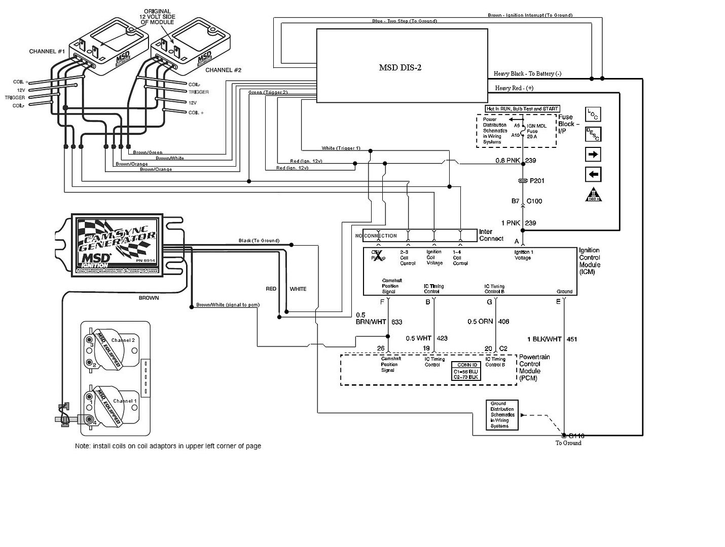
ok ive been preparing to install this setup on my car for a while, and i decided to make a diagram first. note: not complete! I dont have the cam sync generator wired into the CSI pickup in this image, and i also didnt put the actual MSD coils in. channel one is for cylinders 1 and 4, and channel 2 goes to 2 and 3. This diagram is for the DIS-2, msd blaster coils, and spark plug wires as opposed to the stock coils and boots. Im also not SURE about the two red "Ign. 12v" wires coming from the msd and how they attach to the whole setup. other than that... just sharing my ideas with the public.


sorry about the bad pic... now MeltdOwn350 aka cOdy is hosting it for me so we can all be happy!! props to him...


A couple of my thoughts....

sig not found
read the first post. i didnt put the MSD cam sync generator in the pic yet.

Updated, complete version with cam sync generator and corrected Power schematics!!! trash the old one!!


now is all of this proven, by being hooked up and ran on your car?
Or is this what you think will work?
I have been wanting to do something like this but not very good with electrical, and wiring diagrams
If your interested in custom aluminum tilt wheel levers hit me up!
ive already done this with the stock coils and got the motor to fire just getting code 340 which is crankshaft position sensor malf

1989 Turbo Trans Am #82, 2007 Cobalt SS G85
these schematics do agree with mine I have been unable to test the 8914 part

1989 Turbo Trans Am #82, 2007 Cobalt SS G85
do you not have it? or does it not work for some reason.... it seems specifically tailored to our cars though (wiring color is even the same)

no i dont have the 8914 part, its for saturns which is very close to the ecotec in design , the wiring color is the same cause your using an msd part with an msd part

1989 Turbo Trans Am #82, 2007 Cobalt SS G85
check again... the diagram with the PCM and the ICM is direct from the GM service manual for the J car. Now if you look at the ICM wiring harness, youll see "BRN/WHT" on the camshaft position signal wire. I didn't write that. Its from the gm schematic.

i know i have the same diagram

1989 Turbo Trans Am #82, 2007 Cobalt SS G85
ill have the parts soon so i can install the system next weekend,... ill take pics and stuff and post it

saturn eco is the same
just intake is mounted the other way so it should all work

Someone hurry up and do this cause I want to do it in the future
www.kronosperformance.com / 732-742-8837

The only thing I wonder about is how exactly do you tap into the 4th plug wire safely I'm not aware of any type of connector to do this

1989 Turbo Trans Am #82, 2007 Cobalt SS G85
Rodimus Prime wrote:The only thing I wonder about is how exactly do you tap into the 4th plug wire safely I'm not aware of any type of connector to do this
are you reffering to getting signal for the cam sync generator? if that's the case, i thought it just wrapped around the plug wire, kinda like a clamp on ammeter?

wrapping a wire around the plug wire , just seems unsafe, id like to see some type of plug on connector

1989 Turbo Trans Am #82, 2007 Cobalt SS G85
wrapping will work fine as far as i know.. the plugs produce a pretty strony magnetic field when they fire... and as we all SHOULD know... a magnetic field produces electric current, and vice versa. (high school physics 101)

update... i just remembered that the blue (two step) and brown (ignition interrupt) wires do NOT need to be grounded. (two step is the low rev limiter, ignition interrupt im not entirely sure about). grounding the wires will enable these features.

yea i didnt even have either one of those hooked up

1989 Turbo Trans Am #82, 2007 Cobalt SS G85


