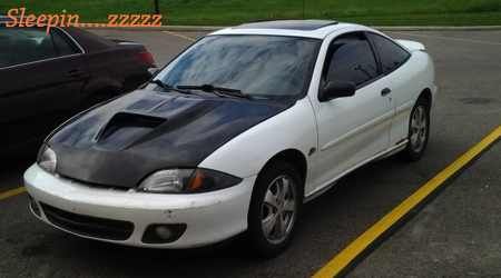
Hey all ,I don't post here anymore due to the fact that I gave up on j-bodies all together!
Thought I would stop in and see if any of you kids were still playing with megasquirt?
and how your experience has been with it?

Gotta squirt'm all.
...
I've been running it a few years with my 3400. Nothing but happy.


Great,
Hey James what board version and code are you running?
have you used any of the msns extras?
you are boost control, knock , egt?
using the oem dis coil pack ..

Gotta squirt'm all.
...
I'm running MS2extra. IIRC it's the 3.57 board. I have probably the simplest setup possible. All motor, basic sensors. I'm not even using the idle control. Factory ICM and coils. The wildest thing I've got is an AEM UEGO. I wanted something that was reliable and changeable so I could upgrade without any major hassles. At some point I plan on exploiting it's ability much more.


I was using ms v1.1 board and msn's'E 024s code.
generic crank wheel decoder ,...so any way I welded the crank toothed wheel so it was a 6-1 instead of 6+1..and controlled the 1995 coil packs with megasquirt...
this forum doesn't see much action anymore ,does it...

Gotta squirt'm all.
...
Most of the "regulars" are still very active on the facebook groups.
PRND321 Till I DIE
Old Motor: 160whp & 152ft/lbs, 1/4 Mile 15.4 @88.2
M45 + LD9 + 4T40-E, GO GO GO
so some still modify these cars then?
haven't worked on a j-body for a while .I'm not complaining I'm just saying I gave up and became one of them!

Gotta squirt'm all.
...
Robbie c wrote:so some still modify these cars then?
haven't worked on a j-body for a while .I'm not complaining I'm just saying I gave up and became one of them!
Unfortunately. I'm about to end up like you though.

"In Oldskool we trust"
Ryan...your so damn close!
PRND321 Till I DIE
Old Motor: 160whp & 152ft/lbs, 1/4 Mile 15.4 @88.2
M45 + LD9 + 4T40-E, GO GO GO
Y3llowCav wrote:Robbie c wrote:so some still modify these cars then?
haven't worked on a j-body for a while .I'm not complaining I'm just saying I gave up and became one of them!
Unfortunately. I'm about to end up like you though.
Nooooo ryan :'-( anything worth having is worth figthing for!!! No matter how hard it is itll be worth it in the end :-)

I Love My J ♡
Is any project really ever ''done'',
anyway like I said ,I gave up on the cavi and now own a civic well 3 actually ,it's older and probably in worse shape than the cavalier was ,but does it ever haul A$$ , .
The car ,the turbo setup, fuel, built engine, new tires, all for under 2500$ !
and being able to run Very low 13's in the 1/4 mile at 9 psi on 87 octane, the honda has been together for 5 years ,1 year at 9psi 3 years at 16psi and for the past year I have the boost at 19-23 psi all on pump gas ...
it makes me wonder why I wasted my time with the J.
Well I do know why ,It was a great learning experience and I enjoyed every minute of it. ....
except getting beat by N/a d16 hatchbacks haha.
so don' t give up on your dreams of owning something you can be proud of.

Gotta squirt'm all.
...
I'm hoping someone can explain this to me, why is it that we can't tap into the crank trigger sensor while trying to run MS in parallel with the factory ECM? I'm running an 01 LD9 and trying to figure out what sensors are sharable and which are not. I've gone through several threads that date back to 2009 and later, but for some reason there hasn't been any real definitive answers posted, at least that I've been able to find.
Can anyone give some updates or explanations on why/why not/what/what cannot, work?
I would greatly appreciate it as this is seemingly going to be my biggest hurdle. I'm REALLY hoping Joshua Dearman chimes in (assuming he still lurks.) As well as Whalesac.

My first thought, off the top of my head....is the crank sensor on LD9s are Magnetic Speed Sensors....they create a voltage. When you tap into the sensor your weakening the signal and messing with the output of the sensor. You can severely mess with the Voltage per pulse of the sensor. You are also changing the resistance of the circuit slightly which also changes the output voltage.
Most hall effect sensors should be able to be shared, but any two wire sensor...I would advise against it.
Being mainly a mechanical engineer that is about the best I can explain it. An electrical engineer should be able to explain it WAY better. Where is
whalesac1 when you need him.
Edited 1 time(s). Last edited Friday, May 30, 2014 11:10 AM
PRND321 Till I DIE
Old Motor: 160whp & 152ft/lbs, 1/4 Mile 15.4 @88.2
M45 + LD9 + 4T40-E, GO GO GO
-MD- Enforcer wrote:My first thought, off the top of my head....is the crank sensor on LD9s are Magnetic Speed Sensors....they create a voltage. When you tape in sensor your weakening the signal and messing with the output of the sensor. You can severely mess with the Voltage per pulse of the sensor. You are also changing the resistance of the circuit slightly which also changes the output voltage.
Most hall effect sensors should be able to be shared, but any two wire sensor...I would advise against it.
Being mainly a mechanical engineer that is about the best I can explain it. An electrical engineer should be able to explain it WAY better. Where is whalesac1 when you need him.
That's awesome, thank you for the explanation! So what would you imagine i could do to either fake a signal or copy the signal to the original ECU, and have the MSII board see the realtime signal coming from the crank?

You could run an external crank trigger, mounted to the crank pulley for Megashirt...
PRND321 Till I DIE
Old Motor: 160whp & 152ft/lbs, 1/4 Mile 15.4 @88.2
M45 + LD9 + 4T40-E, GO GO GO
-MD- Enforcer wrote:You could run an external crank trigger, mounted to the crank pulley for Megashirt...
My bad, i meant to add to the end of that post "without the need of running an external trigger?"
If there's no other way, i guess i'm hosed into getting that to work.

Am I too late?
I have no signiture
I have considered running Megasquirt in the past, but never really got to the point where I needed it to be honest. Currently running HPTuners with Hahn's portfueler setup and the Split Second software...more than good enough for what I need.
Probably V6 swapping it this winter tho with OBD1 and Code59.

Never too late. Info at anytime is good timing.

Quote:
Never too late. Info at anytime is good timing.
Back in the day I put a megasquirt spark and fuel control on a 99 cavi LD9 with auto trans .
I used a coil pack from a 93 cavalier ,the MS had its own coolant ,air temp,O2
and shared the TPS.
I had resistors in the injector plugs to trick the oem pcm to think there was injectors.
but from what I remember the crank sensor was shared.
It's hard to remember 10 years back and not my car ,
THe factory pcm was in place for the trans and connected to all engine sensors so there was no CEL.

Gotta squirt'm all.
...
What Mike posted is correct. The signal that is generated from a VR is very weak. It doesn't take much load to pull it down. This was the issue I had originally with my transmission controller project. The way I fixed it was in a similar manner to the V3.0 board's (and probably 3.57's) optional optoisolator input (with an additional transistor). This provided an isolated high impedance input for the CPS signal.
The method we all used in the past for ignition though was like Robbie mentioned. You use one of the older ICMs and what actually went to the standalone was an already conditioned version of the crank signal. I did some digging around and found an old post of mine that shows the how it's wired....
http://www.j-body.org/forums/read.php?f=64&i=10970&t=10913&p=1
If your plan is to use the stock ICM or COP, then someone else will have to help because I've been out of this game for far too long

I have no signiture
Whalesac wrote:What Mike posted is correct. The signal that is generated from a VR is very weak. It doesn't take much load to pull it down. This was the issue I had originally with my transmission controller project. The way I fixed it was in a similar manner to the V3.0 board's (and probably 3.57's) optional optoisolator input (with an additional transistor). This provided an isolated high impedance input for the CPS signal.
The method we all used in the past for ignition though was like Robbie mentioned. You use one of the older ICMs and what actually went to the standalone was an already conditioned version of the crank signal. I did some digging around and found an old post of mine that shows the how it's wired....http://www.j-body.org/forums/read.php?f=64&i=10970&t=10913&p=1
If your plan is to use the stock ICM or COP, then someone else will have to help because I've been out of this game for far too long 
I am newb (improperly worded sentence for emphasis on newb) so "optoisolator" sounded like a wicked popsicle i used to have as a kid. so i googled it

Quote:
In electronics, an opto-isolator, also called an optocoupler, photocoupler, or optical isolator, is a component that transfers electrical signals between two isolated circuits by using light.[1] Opto-isolators prevent high voltages from affecting the system receiving the signal.
That is copied from Wikipedia. My question now is; in english, does that mean it prevents larger loads from creating a drop in resistance on a wire/circuit, therefore allowing you to duplicate a signal such as a VR signal from a crank?
Meaning, get a V3.57 board and run the crank signal like so: sensor-ICM-ECU-MS3.57-whatever goes next?
Or have i completely misunderstood what i read.

Are you planning to run the JBody ICM or COP for spark? If you use the older Quad4, LN2, Tech4, etc. ICM, then you can tap into the CPS wiring directly and just follow the wiring diagram in the link provided earlier.
I have no signiture


 I Love My J ♡


